
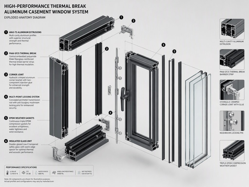
- The profile is the only part of a window that is simultaneously structure, thermal path, weather path and the datum every gasket and hinge is fixed to, so a shortfall there cannot be corrected later by better glass or better hardware.
- Most tenders specify thermal break aluminium without naming an alloy; EN AW-6060 and EN AW-6063 are both used for window profiles and carry different property minima in EN 755-2, which makes the alloy a verifiable clause rather than a category.
- Stiffness of a thin wall in bending scales with the cube of its thickness, so a wall delivered at 1.25 mm instead of 1.40 mm loses roughly a quarter of its bending stiffness while still sitting inside some tolerance classes.
- A caliper taken at the edge of a profile reads high because the die radius is thicker there; the measurement that counts is taken on a flat mid-wall, at several positions, on a square cut.
- The polyamide barrier is the whole thermal claim: strip glass content, knurling, crimp depth and crimp continuity decide both the Uf value and the shear capacity that EN 14024 addresses, and an over-rolled crimp cracks the barrier while a shallow one lets it slip.
- Powder coating and anodizing fail at the pre-treatment line rather than at the polymer, and salt spray hours are a screening result rather than a service life prediction, which is why the coater process sheet belongs in the submittal.
- A mill certificate to EN 10204 type 3.1 ties a delivered lot to a heat number and to mechanical results, and it is the cheapest document in the whole order to ask for and the most useful one to hold.
1. Why the Extrusion Sets the Ceiling on Everything Else
A window is bought as a system, but it fails as a set of interfaces, and nearly every one of those interfaces is machined into the aluminium. The profile is structure: it carries wind load from the glass to the building and it is the only element that resists racking when a door leaf is slammed. It is the thermal path, since the barrier inside it decides the frame U-value before any glass is chosen. It is the weather path, because the drainage chambers, the gasket grooves and the pressure-equalisation slots are all features of the extrusion rather than additions to it. And it is the datum: hinges, lock keeps, friction stays and setting blocks are positioned relative to walls that are supposed to be where the drawing says they are.
Procurement attention does not follow that hierarchy. Glass has a brand, a coating name and a visible effect on the energy calculation. Hardware has a cycle rating and a catalogue. The extrusion arrives by the tonne, is described in the tender as thermal break aluminium, and is priced as a commodity, which is a description of a category rather than of a product. Two suppliers can both quote a thermally broken 6063 system and deliver profiles that differ by alloy, temper, wall thickness, barrier construction and coating pre-treatment, with a measurable difference in service behaviour and almost no visible difference on the day of delivery.
The commercial consequence is asymmetry. A client who is unhappy with acoustic performance can add a laminated pane. A client who is unhappy with a handle can change the hardware line. A client who discovers in year three that the mullion walls are thin, the crimp depth is shallow and the coating is blistering along the mitres has no remedy short of replacement. This is why the questions in this guide belong at the enquiry stage, when they cost nothing, rather than at the inspection stage, when they cost a container.
2. Alloy Grade: 6060 Against 6063, and What the Difference Buys
Architectural window and door profiles are almost always drawn from the 6xxx series, the magnesium and silicon family that gains strength from a magnesium silicide precipitate and can therefore be strengthened after extrusion by artificial ageing. Within that family two alloys dominate: EN AW-6060 and EN AW-6063. Their chemistry is close, and that closeness is exactly the problem, because the tender document usually does not distinguish them and the invoice rarely does either.
The practical difference runs in two directions. 6063 carries a wider magnesium range and delivers the higher proof stress of the pair, together with a surface that responds well to anodizing: the anodic film forms more evenly and reads brighter, which is why architectural anodized work has historically been specified in 6063. 6060 is softer, extrudes more readily, and is often chosen for thin-walled and geometrically complex dies where die wear and extrusion pressure matter more than a few megapascals of yield strength. A fabricator running both alloys is normal; a fabricator substituting one for the other without saying so is also normal, and it is the substitution a buyer has to design out.
Composition is defined in the EN 573-3 standard for wrought aluminium, and mechanical property minima are tabulated by alloy and temper in EN 755-2. Those two documents turn a vague expectation into a testable clause: a delivered profile can be checked by spark optical emission spectrometry in under a minute at a mill, a laboratory or a well-equipped fabricator, and the resulting composition either matches the drawing or it does not. Billet quality is the companion issue, and it behaves differently by finish. Streaks, die lines and inclusions that originate in recycled billet are invisible under a powder coat and obvious under anodizing, so a project specifying anodized finish is buying a stricter billet specification whether it says so or not.
3. Temper: Where T5 and T6 Belong, and Where They Do Not
Alloy sets the composition; temper sets the property. The temper designation is defined by EN 515, and the two that matter in fenestration are T5 and T6. In T5 the profile is cooled from the extrusion press by air or mist and then artificially aged to its final strength. In T6 the profile is solution heat treated, quenched, and then aged, which produces a higher proof stress and a lower elongation at fracture. The difference is not marketing language; it is a defined set of property minima against which a tensile test either passes or fails.
Most architectural systems are developed around T5, and there are sound engineering reasons for that beyond cost. Air cooling leaves far less residual stress than a quench, so long thin sections and complex hollow dies stay straighter and more dimensionally stable through machining, and the die libraries that a system is built on are usually qualified in that temper. T6 is the right answer where the structural demand is genuinely higher: mullions in a tall window wall, oversized door leaves, hardware fixing zones where screw pull-out governs, or a project wind load that has already consumed the margin in the T5 section. It also machines differently, and a design that was detailed for T5 with sharp internal corners can crack in T6 unless the corner radii are opened up.
What follows for a buyer is that the temper is a structural decision and must be traceable to one. A change from T5 to T6 mid-project is not an upgrade in the abstract; it changes the calculation, the machining detail and the flatness of thin profiles, and a change in the other direction can quietly remove capacity. The field proxy is hardness, measured with a portable instrument on a prepared surface, and the authoritative check is a tensile test reported against EN 755-2. Neither takes long, and neither is possible once the profiles have been cut and assembled into frames sitting in a container.
4. Wall Thickness, Section Modulus and the Cube in the Equation
Wall thickness is the single most consequential dimension in a window profile and the one most often treated as approximate. For a thin wall bending about an axis parallel to its face, the second moment of area goes with the cube of the thickness. The consequence is not intuitive to anyone who has not done the arithmetic: a wall delivered at 1.25 mm instead of a nominal 1.40 mm is about eleven percent thinner and loses roughly a quarter of its bending stiffness. At 1.20 mm against 1.40 mm the loss approaches forty percent. The mass falls by the same small percentage, which is why a wall shortfall is commercially attractive and physically expensive.
The effects show up at four specific places. Mullion and transom deflection under wind is the first, and it is the one that gets calculated, because excessive deflection both opens the weather joint and, in a glazed system, transfers movement into the glass edge. Screw pull-out is the second: the capacity of a self-tapping screw in aluminium depends on engaged thread area in the wall it bites into, so a hardware fixing zone drawn at 2.0 mm and delivered at 1.7 mm loses capacity faster than the thickness ratio suggests. Corner joint strength is the third, since a crimped or screwed corner relies on the section available to resist the moment. The fourth is the thermal barrier crimp, where the aluminium wall that is rolled over the polyamide strip has to have enough material to form a continuous mechanical lock.
Measurement is where most inspections go wrong. A caliper applied at the edge of a section reads high, because the die radius and the extrusion flow leave more material at the corner than along the flat. The reading that means anything is taken on a square cut, on a flat mid-wall, at three or more positions along the profile, and compared against the drawing and the applicable tolerance. Mass per metre offers a fast cross-check: theoretical mass from the section drawing at 2.70 grams per cubic centimetre against the weighed mass of one metre of profile. It is a screening tool rather than proof, because alloy and barrier content both shift the number, but a consistent shortfall across a lot is worth a conversation.
5. Tolerances on Dimensions and Form: What Ships Against What Is Drawn
A drawing states nominal dimensions; a standard states how far a delivered profile may sit from them. For window work in a European specification the relevant document for precision profiles is EN 12020-2, which covers tolerances on dimensions and form for extruded precision profiles in EN AW-6060 and EN AW-6063 and, just as importantly, defines how each dimension is to be measured. General extruded profiles fall under the EN 755 series, where the tolerances on dimensions and form are wider. Precision profiles exist as a separate class because fenestration needs them to: a gasket groove that is a few tenths out will not retain its gasket, and a hardware chamber that is out of position will not accept a lock body.
Form tolerances matter more in fabrication than buyers expect. Straightness, twist and camber are not visible on a two metre sample held at arm's length, but a frame built from profiles with residual twist will not sit flat on an assembly bench, and the fabricator will straighten it, select from stock, or shim it, all of which cost labour and leave locked-in stress that reappears as a sash that will not pull tight against its gasket a year later. Length tolerance and cut squareness compound the same way across a multi-panel run.
Two purchasing points follow. First, a tolerance is a manufacturing allowance, not a design target: a system detailed to the low limit of a tolerance class has already spent its margin before the first profile is cut, and the sensible specification states what the assembly can tolerate rather than what the standard permits. Second, the tolerance class, the measuring method and the sampling rate belong in the purchase order, together with a right of rejection on a sampled basis. Without those three, the standard is a document the mill holds and the buyer does not.
6. The Thermal Barrier: Polyamide Strip, Crimping and Composite Capacity
Aluminium conducts heat at roughly two hundred watts per metre-kelvin; the polyamide used in thermal barriers conducts at around a third of a watt. That thousand-fold difference is the entire thermal claim of a thermally broken system, and it is carried by two narrow strips, typically around twenty-five percent glass fibre reinforced, that separate the inside face of the profile from the outside face. The barrier is not an insert added at the end of the process; it is a structural element of the composite profile, formed by knurling or serrating the polyamide, inserting it into the aluminium, and then mechanically rolling or crimping the aluminium over it.
The alternative construction pours a two-component polyurethane bridge into a cavity in the profile and then cuts away the aluminium web behind it. Both are legitimate; both fail in the same two ways. The first is a shallow, intermittent or missed crimp, which leaves the strip held by friction over part of its length and allows progressive slip under sustained shear, with the visible symptom being a frame that slowly loses its dimensional relationship between the inner and outer faces. The second is an over-rolled crimp, which cracks the glass-filled polyamide at the serration root and converts a mechanical lock into a line of stress concentrations. Strip that is not fully seated, or that has absorbed moisture before assembly, produces a gap that is both a thermal bridge and a water path into a cavity nobody inspects after the frames are glazed.
Mechanical performance of the composite profile is addressed by EN 14024, which sets out requirements, proof of performance and test methods for metal profiles with thermal barriers, covering the shear and transverse tensile behaviour of the assembly. For a buyer, the practical checks are a documented test record from the system supplier, a visual inspection of crimp continuity along the full length of a sample profile, and a pull-out or shear test on a cut section. Barrier width is the design trade-off to understand: a wider barrier improves the frame U-value and simultaneously reduces the composite stiffness, so tall or heavily loaded units are normally served by a deeper profile rather than by a wider barrier alone.
7. Surface Finish Is a Corrosion System, Not a Colour Selection
Anodizing, powder coating and liquid fluoropolymer coating are usually discussed as appearance, and they are really a corrosion control system whose weakest link is almost never the topcoat. Three families cover most architectural work. Anodizing builds a controlled aluminium oxide film through the surface itself, and the film thickness classes and sealing requirements are set out in EN ISO 7599, with architectural requirements addressed separately in specifications such as AAMA 611. Powder coating applies an organic film over a pre-treated surface, with performance tiers distinguished by exposure duration and by gloss and colour retention thresholds in specifications such as AAMA 2603, 2604 and 2605, and by the EN 12206 series for organic coatings on aluminium. Fluoropolymer liquid coatings sit at the top of the same performance ladder and are chosen for colour stability rather than for barrier thickness.
What determines service life is the pre-treatment line. Degreasing, etching, desmutting, conversion coating and rinse water quality decide whether a cured film is adhered to aluminium or merely resting on it. A sixty micron powder coat over a poorly converted surface fails by blistering and filiform corrosion spreading from a scribe or a cut edge, and it fails in coastal and industrial atmospheres within a timeframe that a warranty conversation will not survive. Cut edges, mitred corners, screw holes and the drainage slots are where that failure begins, because they expose bare metal or a film that has been severed.
Salt spray testing to EN ISO 9227 is a screening comparison between finishes, not a prediction of service life; a thousand hours of neutral salt spray does not translate into a number of years on a facade, and quoting it as though it does is a common and unhelpful habit on both sides of the transaction. The purchasing answer is a process sheet rather than a sample plaque: which pre-treatment stage and chemistry, which coating product and code, which dry film thickness range, which performance tier, and whether the coating is applied to all faces or to visible faces only. A coater who can produce that sheet is describing a line; a coater who cannot is describing a colour.
8. Verification: Mill Certificates, Incoming Checks and Purchase Order Clauses
None of the preceding matters unless it can be confirmed before the material is consumed. The foundation document is a mill certificate issued to EN 10204 type 3.1, which ties the delivered lot to a heat number and reports the mechanical results for that heat as certified by the manufacturer's independent inspection representative. It converts a conversation about alloy and temper into a traceable record, and it is the cheapest document in the entire order to request. The table sets out the checks that belong on an incoming inspection record and what each one actually proves.
| Check | Method | What it demonstrates |
|---|---|---|
| Alloy composition | Spark optical emission spectrometry | That the delivered metal is the alloy on the drawing rather than a look-alike substitute |
| Temper | Mill certificate against EN 755-2, plus portable hardness as a proxy | That artificial ageing produced the specified property minima |
| Wall thickness | Caliper on a square cut, flat mid-wall, three or more positions | The section that the deflection and pull-out calculations assumed |
| Form | Straightness, twist and camber against the stated tolerance class and method | That frames can be assembled flat without correction |
| Mass per metre | Weighed one metre section against theoretical mass at 2.70 g per cubic centimetre | A fast screen for a systematic wall shortfall across the lot |
| Thermal barrier | Crimp continuity by eye, plus shear or pull-out on a cut sample | That the composite profile behaves as the system was qualified |
| Coating | Dry film thickness by magnetic gauge for powder, eddy current for anodizing, plus the coater process sheet | That the specified finish system was applied over a controlled pre-treatment |
The clauses that make those checks usable are short. They name the alloy and temper with the standard that defines them, they name the dimensional standard and tolerance class with the measuring method, they require a mill certificate to EN 10204 type 3.1 with each lot, they require the coating supplier and product code with the dry film thickness range, and they reserve the right to reject on a sampled basis. The record that travels with the delivery should link each unit to a heat number and a coating batch, so that a defect six months later can be traced to a lot instead of to the whole order. The extrusion is the one part of a window that appears in no brochure photograph, and it is precisely the part that cannot be improved once the contract has been signed.
Explore OPPGATE Aluminum Windows
Thermal break aluminum sliding, casement, tilt-and-turn and panoramic window systems for global residential and commercial projects.
View All Aluminum Windows Models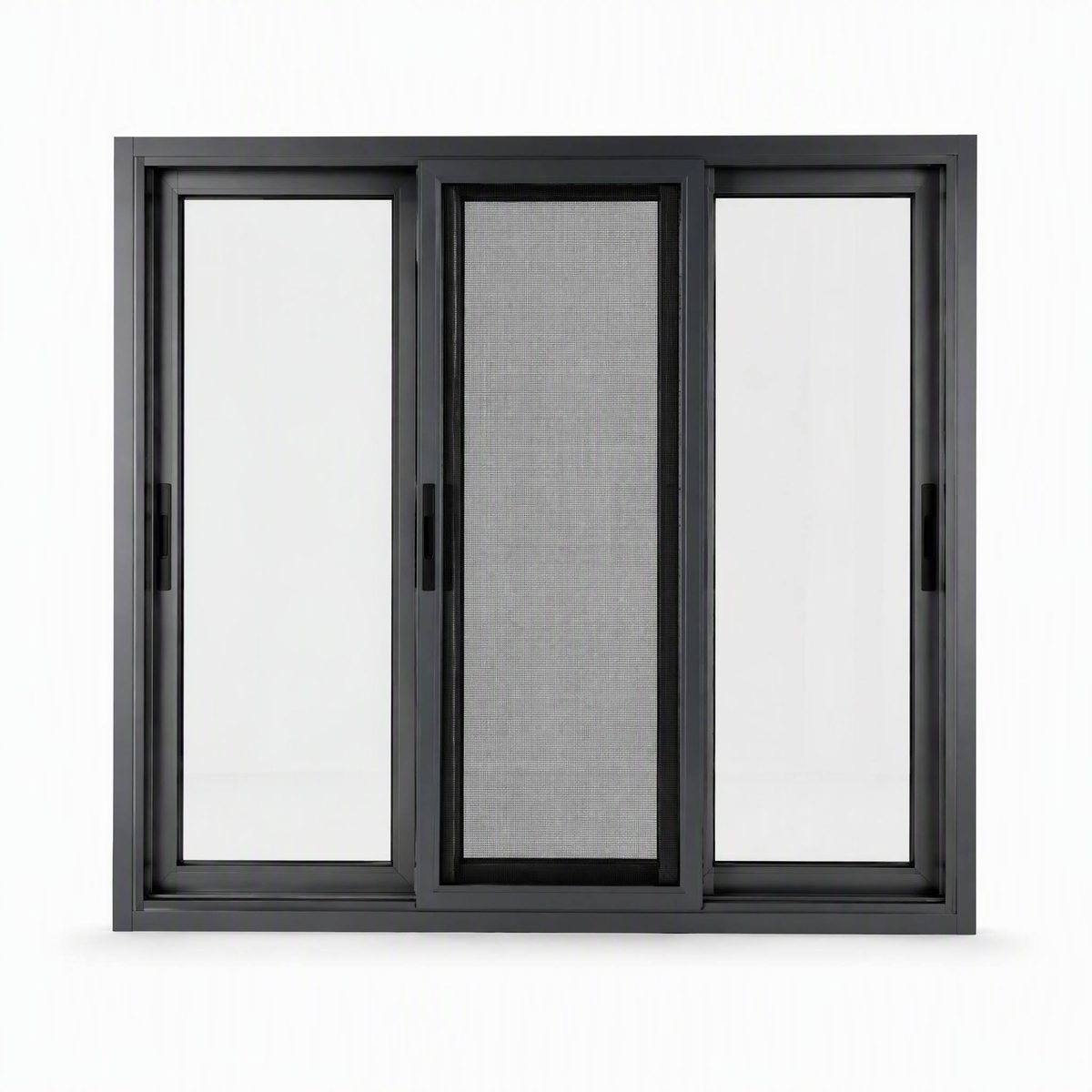
Planning a Commercial or Villa Project?
Send your window schedules or architectural CAD drawings to the OPPGATE engineering team for a prompt, certified quotation and structural review.
Request an Engineered Quotation