
- A component certificate is issued for one design at one reference size with one glazing build; the same frame at a larger size calculates a different U-value because the frame-to-glass ratio changes.
- The window U-value is an area-weighted average of frame, glass and spacer perimeter term, so a compact openable window with a quarter to a third of its area in frame cannot be rescued by better glass alone.
- A triple unit of three 4 mm panes weighs about 30 kg per square metre against 20 kg for a conventional double unit, and that difference lands on hinges, corner joints and operating hardware.
- Installed performance depends on where the frame sits relative to the insulation; a window set in the structural opening with an uninsulated reveal loses more than most glazing upgrades recover.
- Air leakage at the frame is usually a trade-interface gap rather than a product defect, so the airtight layer needs a named owner in the same clause as the window.
- A cold-climate window optimised for winter still overheats in July; DIN 4108-2 rewards external shading and orientation-specific glazing far more than a lower U-value.
1. What a Component Certificate Covers, and What It Does Not
A window described as suitable for a Passive House is not automatically a certified component, and the difference matters far more in procurement than in marketing. The Passive House Institute publishes a component database in which windows appear with a component identifier, a declared window U-value, the reference size at which that value was determined, the glazing build and spacer used in the calculation, and the climate zones for which the data set was produced. The entry is therefore a statement about one defined design, evaluated by one defined method, at one defined size.
Three consequences follow. First, the declared value belongs to the reference size: a compact reference window carries a higher frame fraction than a large one, so the same section calculated at a bigger size returns a better U-value and the certificate figure cannot simply be pasted onto a schedule. Second, the entry is tied to the glazing it was calculated with, so a project that changes cavity width, coating or spacer type is no longer looking at the certified combination even when the frame is identical. Third, and most often forgotten, a component certificate verifies a design and its calculated performance. It says nothing about factory production control, and nothing at all about how the window behaves once it is fixed into a wall.
For a buyer the useful discipline is short: ask for the component identifier, read it against the published entry, and compare reference size, glazing build, spacer type and climate zone against the project requirement. A product that reaches the required figure without certification is a legitimate engineering outcome; it simply has to be demonstrated by calculation and test evidence rather than by a database reference, and the enquiry should state which route the project will accept so that the two are never compared as if they were the same thing.
2. The Arithmetic Behind a Window U-Value
The window U-value is an area-weighted average, and that single fact explains most of the design decisions that follow it. In the method of EN ISO 10077-1 the heat loss of the assembly is assembled from three contributions: glazing area multiplied by its U-value, frame area multiplied by the frame U-value, and the length of the glazing perimeter multiplied by the linear thermal transmittance of the spacer and edge seal. The three are summed and divided by the total projected area of the window. Where the frame value is not taken from a tabulated default, it is obtained by the numerical method of EN ISO 10077-2, and the glazing value from EN 673.
Two features of that formula drive specification. The frame is not a small part of the assembly: on a compact openable window a quarter to a third of the projected area can be frame, and a frame generally insulates less well than the glass it holds, so a very good glazing build cannot rescue an indifferent section. The spacer, meanwhile, is charged per metre of glazing perimeter rather than per square metre of glass, which is why a warm-edge spacer earns most of its value on small lights, and why one window divided into several panes performs worse than a single large light of the same overall size in the same section.
This is also why a headline U-value is only meaningful with its context attached. The same section quoted at two sizes produces two figures, and a figure quoted without reference size, glazing build and spacer cannot be compared with a competitor's number. A well-formed enquiry asks for the calculation rather than the conclusion, in the layout of EN ISO 10077-1, so that the areas, the frame value and the perimeter term are all visible and can be reconciled against the shop drawing. When a supplier cannot produce that reconciliation, the number on the datasheet is a claim rather than a result.
3. Depth, Weight and the Consequences of a Triple Unit
Cold-climate performance pushes the assembly towards deeper frames and heavier glazing, and both have consequences that a section drawing does not show. A triple-glazed unit for a low-energy project is typically 40 to 52 mm thick, with two low-emissivity coatings and an argon or krypton fill, and it needs a frame deep enough to hold it with adequate rebate, correct gasket contact and a warm-edge spacer that is not short-circuited by the bead. Frame depths in the region of 80 to 90 mm are common for that reason, and much of that depth is occupied by a thermal break wide enough to keep the inner and outer shells genuinely apart.
Weight is the constraint that surprises project teams late. Glass weighs about 2.5 kg per square metre per millimetre of thickness, and cavities add thickness without adding weight, so a 40 mm triple unit built from three 4 mm panes is roughly 30 kg per square metre against about 20 kg for a conventional double unit of 4 mm panes. On a tall tilt-turn sash that difference arrives at the hinges, the corner joints and the operating hardware, and it decides whether the sash can still be adjusted to run true after a few seasons of use. The honest design response is smaller sashes, heavier hardware and a reinforced sash profile, not a thinner pane.
Condensation follows the same geometry as the heat flow. The coldest internal surface of a window is normally the junction between the glazing edge and the frame, and the risk of surface condensation there is assessed through the temperature factor of the detail, calculated on the basis of ISO 13788 and compared with the internal humidity the building is designed for. A frame with an aluminium inner shell and an inadequate break will show a wet line along the bottom rebate on the coldest nights of the year even when its average U-value reads well, because an average says nothing about the coldest point on the assembly.
4. Installation Is Where the Calculated Value Is Lost
The performance a low-energy window delivers in service is decided less by the component than by the junction it sits in. Published data for installed performance depends on how the frame is positioned relative to the insulation, and the difference between a window set in the plane of the structural opening and one set forward into the insulation layer is worth more than most glazing upgrades. In the first case the reveal is uninsulated and the heat path runs from the warm internal surface through the frame, around the reveal and out; in the second the frame is overlapped by insulation on three sides and the junction can approach the performance of the wall itself.
That junction carries its own linear thermal transmittance, calculated to EN ISO 10211 for the actual construction rather than lifted from a generic table. The figure that matters in the energy balance is the installed value, which combines the window U-value with the installation thermal bridge over the perimeter, and it is this number the low-energy design methods actually use. Design intent is captured in a detail drawing and not in a note: the position of the frame in the wall, the thickness and continuity of insulation across the reveal, the sub-frame or bracket that carries the window, a sill with slope, drip and thermal separation, and the exact point where the airtight layer connects.
Two failures recur on real projects. The first is an insulation layer that stops neatly at the frame because the reveal was built and closed before the window arrived, leaving a cold bridge around the full opening that no glazing specification can offset. The second is a sill detail that is thermally correct and hydraulically wrong: the window is set deep, the sill has insufficient projection and fall, and wind-driven rain is returned to the frame and the wall below. A deeply recessed opening that looks exemplary in section still receives rain.
5. Airtightness: A Sequence Problem, Not a Product Problem
In a low-energy building the airtight layer is a designed system and the window is one of its components. The result is demonstrated by a pressurisation test to ISO 9972, and the reported number is the air change rate at 50 Pa for the whole dwelling. What that test does not reveal is where the leaks were, which is why the practical question is how the membrane on the inner face of the wall is joined to the frame, and who is responsible for that joint.
Responsibility for it is the most common contractual gap on a low-energy project. The envelope contractor's membrane is drawn to be taped to a clean frame surface; the window arrives with a protective film, a gasket and fixing straps in the way. Each trade completes its own scope correctly and the interface between them belongs to nobody. The details that work are unglamorous: a pre-compressed joint sealing tape or a vapour-tight membrane bonded to the frame before the window is fixed, a vapour-tight seal on the inside face and a vapour-open seal outside, and a sill that drains outward rather than into the wall build-up.
Ventilation belongs in the same conversation, because a background vent or trickle ventilator is a deliberate hole in the airtight layer. In a building served by mechanical ventilation with heat recovery, the ventilation strategy is the ventilation, and an additional uncontrolled inlet is a defect rather than a feature. Where a local rule requires a vent, it belongs in the airtightness calculation and the energy balance from the start, not in a variation added after the test has been booked.
6. Summer Comfort: The Trade-Off a Cold-Climate Window Makes
A window optimised for a Central European winter can make a well-insulated room uncomfortable in July, because the choices that keep heat in also keep solar gain out. A low solar factor limits gain all year: useful in summer, and unhelpful in winter when the solar contribution through a south-facing window is genuinely part of the energy balance. The resolution is rarely a different coating on the same glass everywhere. It is orientation-specific specification, with different builds on different facades, supported by shading that is external and adjustable rather than a blind hanging behind the glass.
Summer performance is normally checked rather than assumed. In Germany the method of DIN 4108-2 assesses the solar load on a room through a simplified solar input coefficient that accounts for window area, orientation, glazing transmittance, shading and the thermal capacity of the construction, and compares the result with a limit that depends on ventilation and internal loads. The calculation rewards modest glazing areas on west facades, effective external shading and high thermal mass, and it penalises large unshaded east and west glazing whatever the U-value of the glass. A specification that fixes a U-value and stays silent on shading has solved half of one problem.
Dark finishes add a summer effect that is seldom considered at tender stage. Solar absorption raises the surface temperature of the frame and the edge of the sealed unit, which increases thermal movement and raises the temperature the spacer and sealant experience; it also raises the pressure inside a sealed cavity. Where a project wants a dark finish on a large south or west elevation, the coating system, the sealed unit specification and the fixing and coupling details should all be agreed with that exposure in mind rather than inherited from a north-facing typical.
7. The Document Set That Separates Verification From Claim
Documents decide whether a low-energy performance figure is a contractual fact. The table below sets out what to request where performance is a requirement, and what each item actually demonstrates.
| Item | What to request | What it demonstrates |
|---|---|---|
| Component entry | Component identifier, reference size, declared U-value, glazing build, spacer type and climate zones | That a defined design was evaluated by a published method at a stated size |
| U-value calculation | Calculation to EN ISO 10077-1 showing areas, frame value and perimeter term, with the EN ISO 10077-2 frame report behind it | That the declared figure reconciles with the drawing being supplied |
| Installation junction | Linear thermal transmittance to EN ISO 10211 for the project detail, not for a generic condition | That installed performance was designed, not just the component |
| Product declaration | Declaration of performance to EN 14351-1 with air, water and wind classes | That market obligations are met, which is a separate matter from any energy scheme |
| Production control | Valid factory production control certification with its audit date and scope | That the evaluated design is being manufactured consistently |
| Glazing evidence | Sealed unit specification as supplied, including pane thicknesses, coatings, gas fill and spacer | That the unit inside the frame matches the unit inside the calculation |
| Size extension | Written statement of the size limits to which the evaluated performance may be applied | That the project sizes are inside the evidence, not outside it |
Two of these are routinely missing and both are easy to ask for. The size extension is the one that decides whether a large fixed light or a tall door leaf is covered by evidence produced on a compact reference window. The installation junction is the one that decides whether the beautiful component figure survives contact with a masonry reveal and a steel bracket. Neither is an unusual request, and a supplier who works regularly with low-energy projects will have both ready.
8. Site Verification and the Failures That Appear in Year Two
The final check is the cheapest one. A mock-up of a single opening, built with the actual frame, the actual insulation and the actual airtightness detail, settles in an afternoon what a schedule of correspondence cannot. Once that opening is signed off, the same routine can be applied to every window on the job in a few minutes each: the frame is at the designed depth in the wall, insulation closes across the reveal with no gap behind the frame, the airtight tape is continuous and bonded to a clean surface rather than to a gasket, the sill projects and falls, and the drainage path in the frame is clear and not bridged by sealant.
The failures that appear in the second year rather than the first follow a short list. A sash that no longer closes cleanly usually indicates fixings over-tightened against packers, leaving the frame bowed. A wet line at the bottom rebate in cold weather indicates a blocked drainage slot or a spacer bridged by a bead. A draught discovered behind a dry lining indicates a tape that was cut and never re-sealed when a service was run. A cold patch at a reveal corner, visible on a winter thermographic survey of the kind described in standards for qualitative inspection, indicates insulation that was compressed or omitted at the most awkward point of the detail. None of these is a glazing failure, and all of them are attributed to the window.
- At what reference size, and with which glazing build, was the declared U-value determined, and does the project size fall inside the stated limits?
- What is the calculated installation thermal bridge for this wall build-up, and which drawing does it belong to?
- Who owns the joint between the wall membrane and the frame, and what is inspected before the reveal is closed?
- How was summer performance checked for the west and east facades, and what shading is included in that check?
- Which test demonstrates airtightness on this project, at what stage, and who attends?
- What maintenance does the hardware and the drainage path need, and who is contracted to do it?
None of this makes a low-energy window complicated. It makes it a system, in which the component, the junction and the site sequence have to be specified together. The projects that achieve the figures they designed for are rarely the ones with the best datasheets; they are the ones that asked for the calculation, drew the junction and inspected the tape.
Explore OPPGATE Aluminum Clad Wood Windows
Architectural windows pairing solid interior timber aesthetics with exterior weather-resistant powder-coated aluminum.
View All Aluminum Clad Wood Windows Models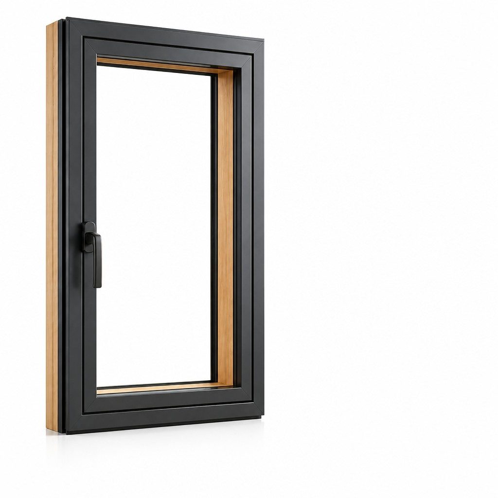
Planning a Commercial or Villa Project?
Send your window schedules or architectural CAD drawings to the OPPGATE engineering team for a prompt, certified quotation and structural review.
Request an Engineered Quotation