

- In a coupled run the frame stops being a perimeter and becomes a beam, so deflection rather than stress normally sets the mullion depth.
- Glass weighs about 2.5 kg per square metre per millimetre of thickness, which turns a stacked transom into a load-bearing member that is often sized for wind alone.
- Aluminium moves roughly 23 x 10^-6 per kelvin, so a six-metre run changes length by several millimetres between a cold night and a sunlit afternoon.
- A coupling joint that is sealed to be watertight but has no vent destroys pressure equalisation, and turns the bay into a reservoir.
- A report issued for a single sash does not cover a six-metre coupled assembly; the specimen size and coupling configuration belong in the enquiry.
1. A Run of Windows Is Not a Bigger Window
Fenestration is priced per opening and engineered per opening, and that habit survives into assemblies where it no longer applies. A schedule line reading four casements with fixed lights above, six metres wide overall, is quoted as one item, delivered as one crate and installed as one operation. Structurally it is not one window. It is a small frame system in which the intermediate mullions carry wind load shared from two bays, the transoms carry the dead weight of the glass above them, and the coupling joints have to absorb the movement of the whole run.
Three consequences follow for anyone specifying or buying the assembly. The load path changes: a single window transfers wind load from sash to frame to the structural opening, while a coupled run transfers load along the run and only then to the structure, so the depth of the intermediate mullion decides the serviceability of every bay it serves. Movement accumulates: each bay expands and contracts, and the sum arrives at the end couplings and at the head and sill fixings. Drainage becomes shared infrastructure: one chamber, one set of weeps and one vent path may serve several bays, and a single blocked outlet affects them all.
This is also why the performance of a long run cannot be inferred from the performance of one unit. A test specimen of modest size exercises a single frame with four corners. A six-metre run exercises intermediate mullions in bending, transoms in vertical load, couplings in shear and drainage in a configuration that only exists at length.
2. Deflection, Not Stress, Sets the Mullion Depth
Aluminium alloy extrusions used in fenestration are strong in relation to the loads a facade carries, so a mullion sized purely by stress calculation usually comes out shallower than the assembly can tolerate. What governs in practice is serviceability. Under design wind pressure, calculated from the wind actions in standards such as EN 1991-1-4 or from the project's code of record, the mullion must not deflect far enough to distress the glass it supports, to break contact with the compression gaskets, or to make an opening sash difficult to operate.
A common convention in North American practice is to limit mullion deflection to span/175 under design wind load, with tighter limits such as span/250 applied to vision areas or where brittle interior finishes meet the frame. European specifications frequently state an absolute limit in millimetres derived from the glass supplier's edge stress allowance instead of a ratio. Neither approach is universal, and the specification should state the limit explicitly rather than leave the supplier to choose a comfortable one. Two related checks matter as much as the ratio itself: the mullion deflection adds to the deflection of the glass, and it is the combined movement at the glazing rebate that loads the edge seal of an insulating glass unit; and the residual permanent set after the load is removed must stay small, because a mullion that returns bowed has already opened its seals.
Deflection is measured, not asserted. A structural performance test to ASTM E330 loads the specimen with a uniform static air pressure difference and records deflection at design pressure, then permanent deformation after release. When a supplier offers a coupled system, the useful question is at what span and at what design pressure the deflection figure was measured, and whether the tested mullion is the section being supplied.
3. Dead Load Has to Have Somewhere to Go
Glass is heavier than most drawings imply. Soda-lime float glass weighs approximately 2.5 kg per square metre per millimetre of thickness, so a 28 mm double-glazed unit is around 70 kg per square metre and a 3 m by 2.5 m light of that build exceeds half a tonne. In a single window that weight lands on setting blocks in the bottom rail and is passed to the sill. In a coupled run it can arrive in the middle of the assembly instead, through a transom, and that is where assemblies are most often under-designed.
The load path must be drawn rather than assumed. Setting blocks are positioned to carry the glass near its quarter points, in a material that will not migrate or take a permanent set, and the rail beneath them must be able to transfer that concentrated load. Where fixed lights sit above an operating sash, the transom carries the glass above plus any wind load on it, and it delivers that load into the mullions at each end. If those mullions are not designed as load-bearing members, or if the coupling between stacked units transmits only lateral load, the transom sags, the sightline bows and the sash below loses its clearance.
Two further details decide whether the calculation survives site conditions. The first is how the assembly meets the structure: head-fixed with the sill free, sill-bearing with a head restraint, or both fixed, which is common and frequently wrong because it locks the frame against the movement it needs. The second is packing and shimming at the fixings, including whether packers are structural or merely alignment aids, and whether the frame bears on a continuous support or on four bolts. A coupled run that is fixed at both ends to a slab that itself deflects will be loaded by the slab, and the frame becomes part of the structural system whether or not anyone designed it that way.
4. Movement Is Where Coupled Assemblies Buckle and Leak
Aluminium expands by roughly 23 x 10^-6 per kelvin. Across a six-metre run, a forty-kelvin swing between a winter night and a sunlit summer afternoon changes the length by about five and a half millimetres. That is small in absolute terms and entirely sufficient to bow a mullion, open a gasket line, crack a powder-coat at a rigid joint, or shear a bead of sealant that was expected to accommodate it.
Thermal movement is only one of several acting on the same detail. Structural movement adds slab deflection under live load, column shortening, concrete creep and shrinkage, and in seismic regions the drift between floors permitted by the seismic design rules. Framing materials differ as well: aluminium to uPVC, aluminium to timber, and aluminium to masonry all move at different rates, and a masonry surround grows with moisture while a concrete one shrinks as it dries. Each interface needs a decision about which side moves and which side is restrained.
The practical vocabulary is unglamorous: slotted holes with washers that allow sliding without losing clamp, oversize holes with a defined clearance, shear blocks that take lateral load while permitting longitudinal movement, baffles and cover caps that hide the joint without locking it, and movement joints at floor lines where a window wall spans between slabs. Each coupling in a long run should be detailed as either fixed or sliding, and the drawing should say which. A coupling that is screwed tight at both ends with no allowance is a rigid tie, and the run will find the weakest point and open it. The visible symptom is usually a gap at a mitre or a sealant bead that has torn, months after handover, in the first week of real temperature range.
5. Drainage and Pressure Equalisation Across the Joint
Water management in a window depends on a drained and vented chamber behind the outer seal, where pressure can equalise with the outside so that water is not pushed inward by a pressure difference. In a coupled assembly the chamber question becomes a system question: is the chamber continuous through the coupling, or is each bay independently drained and vented? Both arrangements work. A mixture of the two does not.
A continuous chamber needs the coupling to be open enough to equalise pressure and continuous enough at the base to carry water to an outlet. An independent bay needs its own weeps and its own vent, and a baffle at the coupling that stops water crossing into the neighbouring unit. The common failures are specific. Sealant applied across a coupling joint during installation bridges the drainage path and creates a dam. A gasket or a foam filler blocks the vent, so the chamber cannot equalise and the outer seal is loaded by pressure it was never meant to resist. A transom that collects water from the light above discharges it into the head chamber of the unit below, which has no outlet at that level. And at the base of the run, sill drainage is asked to deal with water gathered from six metres of elevation.
Reversing the lap is the detail that solves most of this: water from an upper level should be discharged to the outside face, or into a dedicated channel that leads there, never into the head of the unit beneath. Where an internal discharge is unavoidable, the receiving member needs its own collection and outlet. None of this is visible on a general arrangement drawing at 1:50, which is why the coupling details belong in the submittal package and why a mock-up with a hose test settles arguments that drawings cannot.
6. Clamped Glazing or Structural Sealant: Two Different Maintenance Futures
Coupled systems retain glass in one of two ways, and the choice affects maintenance more than appearance. Mechanically clamped glazing uses a pressure plate or bead cap with gaskets, so the glass can be removed and replaced from the outside or inside without dismantling the frame. Structural sealant glazing bonds the glass to the frame with a structural silicone and dispenses with the external cap, giving a flush facade and better thermal continuity across the sightline, at the cost of a bond that cannot be inspected and cannot be renewed in place.
Structural bonding is a system, not a product choice. In Europe the relevant framework is an assessed structural sealant glazing kit under ETAG 002, in which the system holder defines the sealant, the joint geometry and the bite width for a given design wind load and glass build; the bite is not a site decision and the sealant is not interchangeable with another manufacturer's. Two-sided and four-sided configurations behave differently under dead load, and the dead load of the glass in a two-sided bond must be carried mechanically rather than by the silicone alone.
For a window wall between slabs, movement is the deciding argument. A bonded joint has very limited capacity to accommodate the relative movement of the frame and the structure, so the system must isolate it, typically through a separate sub-frame or a movement joint at each floor line. A clamped system tolerates more site variation and is the more forgiving choice where the structural opening is not precise. Neither is a shortcut for the movement detailing in the previous section.
7. How Far a Test Report Reaches Into a Coupled Run
Declared performance is attached to a tested configuration, not to a product family. For windows and doorsets placed on the European market the governing product standard is EN 14351-1, with air permeability, watertightness and wind resistance declared against the classification standards EN 12207, EN 12208 and EN 12210 and tested by EN 1027 and EN 12211. For curtain walling kits the relevant standard is EN 13830, with test methods in the EN 12152, EN 12154 and EN 12179 series for air permeability, watertightness and resistance to wind load. In North America the equivalent route is a performance grade under NAFS, with ASTM E283 for air leakage, ASTM E331 for water penetration and ASTM E330 for structural performance.
In every case the specimen is the assembly: frame, glass, gaskets, hardware, drainage detailing and couplings as tested. Extended application rules exist to allow a tested result to be applied to other dimensions within defined limits, and those limits are exactly what a buyer needs to see when the project run is longer than the specimen. A report for a 1.2 m by 1.5 m casement says little about a six-metre run with intermediate mullions in bending and shared drainage, and a report for a coupled assembly of the same section at a shorter span says more than one for a single unit at the same span.
Where a project exceeds the tested envelope, the honest routes are a project-specific laboratory test of the assembly as designed, or a documented extended application with the limits stated. Field testing is a separate check on installation rather than a substitute for type testing: water penetration of installed assemblies can be investigated by methods such as ASTM E1105 or the AAMA 501.2 field spray, and field air leakage by ASTM E783. These confirm that the detail was built as designed and that joints were not bridged on site, which is the failure mode that laboratory testing cannot catch.
8. Specification Clauses and the Questions That Expose a Weak Assembly
A coupled assembly is specified well when each of its load paths, movement allowances and drainage routes is stated and can be checked in a drawing or a calculation. The table below is a workable structure for a specification clause; the questions after it are the ones worth asking before a purchase order is raised.
| Element | What to specify | How to verify it |
|---|---|---|
| Intermediate mullion | Design wind pressure, deflection limit as a ratio or absolute value, and the section depth that satisfies it | Signed calculation plus the tested deflection at design pressure |
| Transom | Dead load from the glass above, plus wind load, with the load path to the mullions stated | Shop drawing detail showing setting blocks, bearing and fixings |
| Coupling joint | Fixed or sliding, expansion allowance in millimetres, sealant and baffle arrangement | Detail drawing at 1:2 and a mock-up assembled before release |
| Drainage | Continuous or independent chambers, weep and vent positions, discharge direction at transoms | Mock-up hose test with the assembly installed as it will be built |
| Glass retention | Clamped with defined gasket and bite, or structural bonding to an assessed kit | System documentation for the bonded option; part numbers for the clamped option |
| Structural interface | Head and sill fixing condition, movement joint at floor lines, packer type | Interface drawing agreed with the structural engineer |
- What is the design wind pressure for the project, and at what span was the supplied mullion's deflection measured?
- Which member carries the glass above each transom, and does the coupling transmit vertical load or only lateral load?
- How much movement does each coupling accommodate, and is that allowance stated in millimetres on the drawing?
- Are the chambers continuous through the coupling or independent per bay, and where does water leave the run?
- What is the largest assembly the type test covers, and does the project exceed it?
- If the glazing is structurally bonded, which assessed system covers it and who calculated the bite width?
- Is there a movement joint where the run crosses a floor line, and who owns that detail between trades?
None of these questions is exotic, and all of them are cheaper to answer at enquiry stage than after the frames are fabricated. On a facade with a handful of long runs, the difference between an assembly that stays true for twenty years and one that leaks in its third winter is rarely the glass and almost always the depth of a mullion, the capacity of a transom and the honesty of a coupling detail.
Explore OPPGATE Aluminum Windows
Thermal break aluminum sliding, casement, tilt-and-turn and panoramic window systems for global residential and commercial projects.
View All Aluminum Windows Models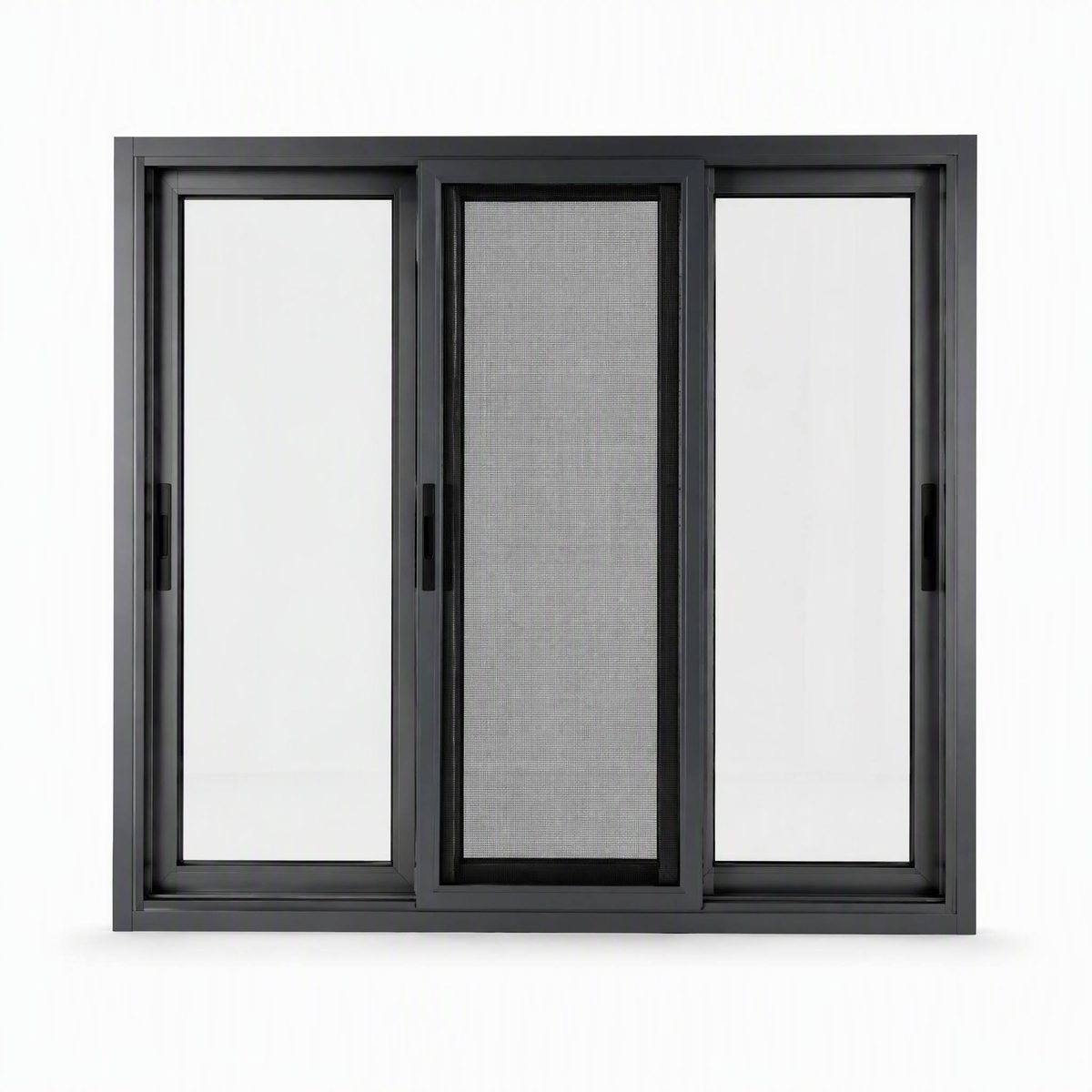
Planning a Commercial or Villa Project?
Send your window schedules or architectural CAD drawings to the OPPGATE engineering team for a prompt, certified quotation and structural review.
Request an Engineered Quotation