
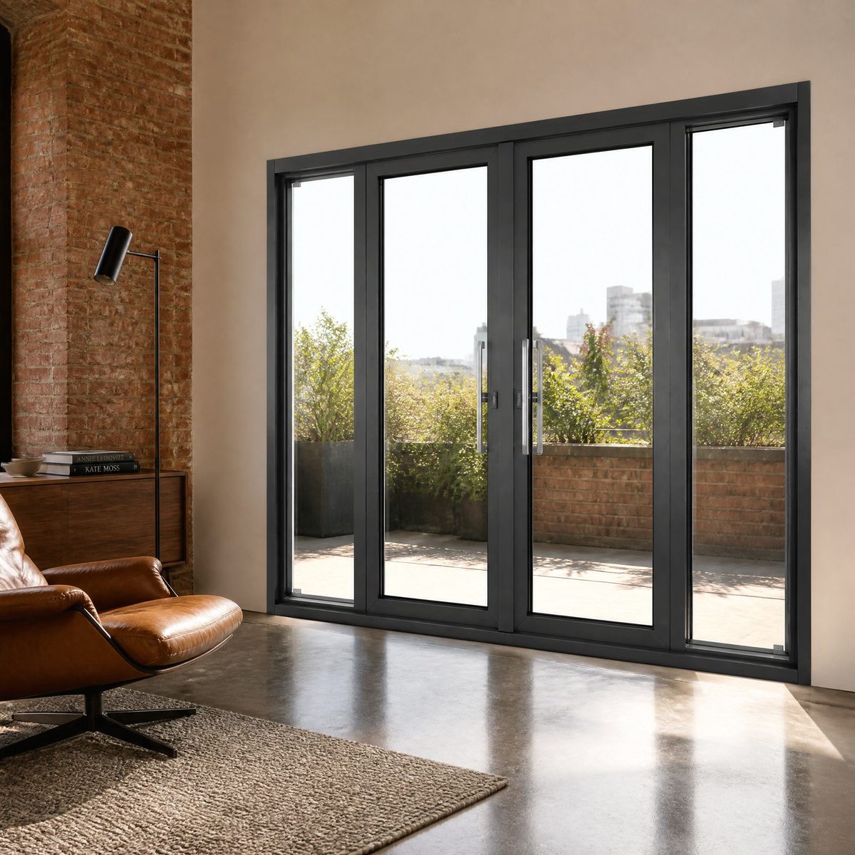
- A folding set is a chain, not a frame: load accumulates along the panels toward the anchored end, so the panel nearest the anchor works hardest while the leading panel carries the handle, the latch and the daily operation.
- Panel count, panel width, folding direction, stack depth and traffic-leaf position are one decision, not five; a set drawn by opening width alone is usually correct on the elevation and wrong in the room.
- Top-hung sets put the weight into the head and leave the floor track as a guide; bottom-rolled sets put it into the floor and raise the threshold. Which is right depends on the structure available, the threshold the project can tolerate and who cleans the track.
- Glass dominates panel weight at roughly 2.5 kg per square metre per millimetre of thickness, so a glazed 1.2 by 2.4 metre leaf already carries close to 90 kg of glass before the frame is counted, and the hardware limit applies to the finished panel.
- A folding door seals in the closed condition only; the hinge line cannot seal at all, so the published air and water classes describe a tested specimen in one configuration and say nothing about a longer set with a different panel count.
- The bottom track is a horizontal water channel: if it is installed out of level or its weeps are blocked by the finished floor, a set that passed a laboratory water test will still leak on site.
- Most folding-door defects are settled in a schedule that records only width and colour; stack zone, head deflection limit, carrier rating, drainage path and the tested configuration are the fields that decide the outcome.
1. A Folding Door Is a Mechanism, Not a Window
A folding door is the only element in a fenestration package that changes geometry while it is in use. A window, a sliding door and even a pivot door keep a fixed number of leaves in a fixed relationship to one another. A folding set unfolds a chain of panels across an opening and then folds the same chain back into a stack a fraction of the original width. That single behaviour explains most of the failures associated with the type, because a chain of panels does not behave like a frame. The load path moves as the door opens, the leaves are connected to each other rather than to a surrounding frame, and the seal is made and broken several times a day for the life of the building.
The consequence for specification is that a folding door cannot honestly be selected from a catalogue by opening size. Panel count, panel width, folding direction, the position of the traffic leaf, the stack zone, the hardware family and the head detail are one decision, not five. Change any one of them and the others move. A set drawn as four equal panels on a three-metre opening will not operate, seal or drain like a set drawn as three panels plus a hinged leaf on the same opening, even though a quotation may describe both as a four-leaf folding door.
The chain is the idea worth holding on to. Each panel hangs from, or rolls alongside, its neighbour. Load accumulates along the chain toward the jamb or the track end where the set is anchored, which means the panel nearest the anchor does the most work while the leading panel carries the handle, the latch and the daily operation. A specification that treats every panel as identical ignores both facts, and the two of them together account for the two most common complaints: a set that becomes heavy to operate, and a leading stile that stops meeting its keep.
2. Panel Count, Panel Width and the Geometry That Fits the Opening
The arithmetic starts with the clear opening, not the structural opening. The clear opening is the width between finished reveals, and it has to be divided into a number of panels whose individual width the hardware can carry, and whose folded stack will still fit inside the room without fouling a return wall, a fixed cabinet run or a floor-level heat emitter.
Three quantities have to be reconciled on the same drawing. The first is the unfolded width, which is the clear opening plus the frame. The second is the folded stack width, which is roughly the width of one panel plus the thickness of every other panel in the stack plus the hardware clearance. The third is the stack depth, which is the projection into the room, and it is the number most often missing from a shop drawing. A set can be perfectly correct on the elevation and unusable in the room because nobody added up the stack.
Folding direction is decided by what the space can lose rather than by what the elevation would prefer. A stack that lands in front of a kitchen island is a design error even when the elevation is symmetrical, and a stack that lands against a return wall needs clearance at the jamb for the first hinge to swing. Where both sides fold, the pair that opens first becomes the traffic route, and the meeting point of the two stacks has to be positioned so the latch is reachable from inside and the panels do not collide at the head when both are folded back at once.
Odd panel counts usually introduce a hinged traffic leaf, and that leaf is a different product from the folding panels: it swings on its own hinges fixed to the frame, carries its own latch and keep, and is often the widest leaf in the set because it has to give a usable clear width on its own. Mixing a hinged leaf into a folding set is normal practice, but it changes the load path at that jamb and it changes the number of seals that have to close for the set to be weathertight. The schedule should say which leaf is the traffic leaf, which way it swings, and whether the folding panels can be operated while it is closed.
3. Top-Hung or Bottom-Rolled: Where the Weight Actually Goes
Two hardware architectures dominate the market, and the difference between them is a single question: which member carries the panel weight. In a top-hung set, each panel hangs from a carriage running in a head track, and the floor track, where one exists at all, only guides the bottom of the leaf and keeps the panels in plane. In a bottom-rolled set the arrangement is inverted: rollers set into the bottom of each panel run on a floor track and carry the weight, while the head track does the guiding.
| Design question | Top-hung set | Bottom-rolled set |
|---|---|---|
| Vertical load path | Panel to hinge to carriage to head track to head member | Panel to roller to floor track to slab or sub-sill |
| Structure required | A head member able to carry the whole set plus wind load, checked at the track line | A floor able to take concentrated wheel loads, and a level track bed |
| Threshold height | Can be low or flush, because the floor track is only a guide | Track depth sets a minimum threshold, which conflicts with level access |
| Sensitivity to debris | Low at the floor, but the head track must stay clear | High: grit, sand and leaf litter on the track reach the wheels directly |
| Adjustment point | At the carriage, usually from the face of the leaf | At the roller, usually from the bottom edge or through an access plug |
| Typical failure signature | Head deflection, carriage wear, panels drifting out of plane | Flat-spotted wheels, worn track, water standing in the channel |
Neither architecture is better in the abstract. The choice is settled by three project facts: whether a structural head is available, how much threshold height the project can tolerate, and who will clean the track. A coastal villa with a flush terrace, a deep lintel and daily housekeeping points one way. A commercial shopfront with a slab soffit, heavy traffic and no cleaning regime points the other, because a bottom-rolled set with a deep track can be swept and hosed, while a top-hung set in the same location hides its mechanism where nobody inspects it.
The load path has to be followed to something that can actually take it. A head track is not a structural member; it is fixed to one. Whether that member is a steel lintel, a concrete soffit or a timber beam, the set's weight, the wind load on the closed panels and the dynamic component of operation all arrive at the fixings. The member therefore has to be checked for deflection along the track line rather than at mid-span of the opening, because the track transmits its load wherever the carriages happen to be. A head that sags a few millimetres across a four-metre opening is invisible on the day of installation and becomes a door that will not latch in the second summer.
4. Hinge Moments, Stile Reinforcement and the Dropped Leading Edge
Every hinge in a folding set carries part of a panel's weight and, whenever the door is part-open, a moment produced by the panel's own centre of mass standing away from the hinge line. That moment is largest when a panel is at right angles to its neighbour, which is exactly the position it occupies during normal operation. Hinge count and spacing are therefore set by panel weight and panel width together, not by the number of hinges that happened to be fitted to the sample that was demonstrated.
Glass dominates the arithmetic, and it is worth doing before the hardware is chosen. A sealed unit weighs roughly 2.5 kg per square metre for every millimetre of glass thickness, so a 6-12-6 unit is about 30 kg per square metre before any frame is counted. A 1.2 m by 2.4 m glazed leaf therefore carries close to 90 kg of glass alone, and triple glazing, a laminated inner pane or a heavier profile wall all add to that figure. The hardware supplier's panel limit refers to the finished panel, not to the glass, and the two are routinely confused in a quotation that lists a glass thickness and a leaf size but never a panel weight.
Reinforcement is what allows a slim stile to carry that load. Folding profiles usually accept a steel or aluminium insert in the hinge stile and in the lock stile, and the hinge screws must engage that insert rather than the 1.4 to 1.8 mm profile wall. Where an insert is omitted to save cost, or where it stops short of the hinge positions, the screws bear on a thin wall that creeps under cyclic load. The failure is gradual and predictable.
It appears as the dropped leading edge. The outermost stile of a wide panel sags, the panel no longer sits square in the opening, the latch misses its keep by a millimetre or two, and the interlock gasket at the meeting stile opens at the top corner. Water then finds the gap on the windward elevation, and the owner reports a door that used to close properly. Nothing has broken; the assembly has simply moved, and the movement is a wear and creep effect that shows up months after handover rather than at commissioning. Checking panel weight against carrier and hinge rating at the drawing stage is the only reliable prevention, because once the set is hung there is nothing left to adjust except the symptom.
5. Sealing: Two Regimes in One Product
A folding door has to seal in two different states, and only one of them can be tested. Closed, the panels sit in line and the joints between them are compression joints: interlock gaskets at each meeting stile, closed by the latch and by the geometry of the rebate. Open or part-open, the same joints are hinges and cannot seal at all. That is not a defect in the product; it is inherent in the mechanism, and it is why the published air and water performance of a folding set belongs strictly to the closed condition.
The practical consequence is that the latch is a sealing device, not only a security device. A multi-point latch that pulls the leading stile into the jamb is what compresses the whole chain of interlock gaskets at once; a single-point latch that only locks the leaf leaves the chain loose, and the middle joints of a long set never close fully. On a four-panel set the difference between a two-point and a four-point latch is the difference between a door that passes its air test on a calm day and one that whistles in a cross wind. Air permeability to EN 12207 and watertightness to EN 12208 are classified on a tested specimen at defined pressures, in a defined size and configuration; the class is a property of that specimen, and a longer set with a different panel count and a different latch has not been covered by it.
Water is the harder problem, because the bottom track of any folding system is a horizontal channel running the full width of the opening. The seal at the hinge line cannot be continuous, so water that reaches the hinge line is managed rather than excluded: it is shed outward by the panel gaskets, collected in the track, and discharged through weeps. That sequence only works if the track is level or falls outward, if the weeps are open, and if the finished floor has not been brought up over the outlet. A set that passed a laboratory water test will still leak on site when the track was installed with a fall toward the room, because the channel then delivers water to the internal upstand instead of to the outside.
Wind-driven rain is the case that separates the details. Under pressure, water is pushed past brush seals and past the first line of gaskets, and the question becomes whether the second line and the drainage path can handle what arrives. This is the reason a folding door is normally specified with a raised threshold and an internal upstand on exposed elevations, and the reason a flush threshold should be treated as a performance decision rather than a styling one.
6. Thresholds, Drainage and the Accessible Detail
Threshold height is where the folding door meets the rest of the building, and it is where two requirements usually collide: a step that keeps water out, and a level access that lets a wheelchair, a trolley or a pushchair through. Three families of detail are in common use, and each of them resolves the collision differently.
- Rebated upstand with a gasket. The most reliable water detail, because the upstand breaks the path that capillary action and wind pressure would otherwise use. It costs a step, typically small but not zero, and it needs a ramped or chamfered edge where access matters.
- Flush track over a drainage channel. Level access is achieved by putting the water channel below the track and giving it a fall to the outside. Performance now depends entirely on the channel: its capacity, its fall, its outlet and the secondary seal between the channel and the internal floor.
- Inset track with a cover plate. A compromise that keeps the track shallow and protected, at the cost of a removable component that has to be lifted for cleaning and that becomes a maintenance item in its own right.
The drainage cavity is a design element, not something left to the installer. Its capacity has to be sufficient for the water arriving during a design storm on that elevation, its falls have to be set before the screed is poured, and its outlet has to remain open for the life of the building. A 40 mm outlet blocked by a sweep of mortar during finishing is indistinguishable, from inside the room, from a seal failure, and it will be diagnosed as one.
Sequence matters more than the drawing. The track is set and levelled first; the screed is brought to the track rather than the track lowered to the screed; the finished floor level is checked against the top of the track; and the drainage path is tested with a hose before the internal finishes are complete. Doing those four things in the other order is the most common reason a level threshold performs badly, and none of them appears on a shop drawing.
7. The Structural Opening: Head, Jambs and the Corner Post
A folding set is a linear mechanism running in a plane, and it is unforgiving about that plane. The head has to be straight and level along the whole travel, the jambs have to be plumb and parallel, and the reveal has to be square. A few millimetres of bow in a four-metre head is enough to make one carriage carry the whole set at mid-travel while the others unload, which converts a smooth door into one that is heavy in the middle and loose at the ends. The same tolerance applied to the jambs produces a set whose panels do not sit in plane when closed, and a gasket that closes at the bottom and gaps at the top.
Where two sets meet at a corner, the corner post stops being trim and becomes structure. It receives the latch keep of one set and the anchor of the other, and it has to be tied back to the building rather than to the window frame it sits beside, because it is now resisting the operating load of two doors and the wind load on both elevations. Corner posts are also where the two drainage paths meet, and the internal upstand has to be continuous around the corner or water simply crosses at the weakest point.
Long runs need expansion provision. Aluminium moves roughly 0.023 mm per metre per kelvin, so a six-metre head track over a 40 K surface temperature swing travels about 5.5 mm. If both ends are anchored hard, that movement goes into the fixings or bows the track, and a bowed track produces exactly the uneven carriage loading described above. Slip joints, slotted fixings or a free end are the standard answers, and the setting-out drawing should show which end is free rather than leaving the choice to the installer.
There is also a size at which folding stops being the right system. As leaves grow, panel weight, stack depth and the wind load on a part-open set all rise together, and a very wide folding door becomes a heavy mechanism that occupies a large part of the room when it is open. Beyond that point a lift-and-slide leaf, or a fixed panel combined with a smaller sliding or folding section, is usually the better engineering answer: fewer moving panels, a lower stack depth and a seal that is made once rather than in a chain. The decision is operational and economic rather than ideological, and it is worth taking before the opening is fixed in the architecture.
8. Specification and Site Verification: The Fields That Decide the Outcome
Most folding-door problems are settled before the first panel arrives, in a schedule that records a width, a height and a colour. A schedule that carries the following fields can be checked by a third party; one that carries only the dimensions cannot.
| Field | What it fixes |
|---|---|
| Clear opening, structural opening and stack zone | Whether the set fits the room when it is open, not only when it is closed |
| Panel count, panel width and folding direction | The traffic route and which jamb carries the anchor |
| Finished panel weight and carrier rating | Whether the hardware is inside its limit before glazing is chosen |
| Hardware family, hinge count and stile reinforcement | The hinge moment the leading stile has to survive |
| Head member type and its deflection limit | What the track is fixed to, and how straight it stays |
| Threshold type, height and drainage path | Whether water leaves the building or the track |
| Seal system at interlock, hinge line and frame | Which joints are compression joints and which are managed |
| Latch type and number of locking points | Whether the interlock chain is actually closed |
| Required air, water and wind class, and the tested configuration | Whether the declared performance covers this size and panel count |
| Adjustment provision and recommended spares | What the maintenance regime can actually do in year five |
On site the sequence is short, and it has to be done in order. Track and head are checked for plumb, level and straightness before any panel is hung. Panel weight is compared with the carrier rating as delivered, not as quoted. The first operation is done by hand with the latch released, so that a binding carriage is felt rather than masked by the mechanism. Latch engagement is then checked at head, middle and sill, because a set that engages only in the middle is already out of plane. The drainage path is tested with a hose before finishes close it off. Finally the set is cycled enough times to reveal a carriage that is binding under load, which a single open-and-close will not show.
Two spares are worth holding from the same production batch as the door: one carriage or roller set, and one hinge. They are the parts that wear, they are the parts whose geometry changes between hardware generations, and a replacement that does not match the original rating will fail faster than the component it replaced. On a building with several identical sets, keeping one panel's worth of hardware in store is a smaller cost than a six-week lead time on a part that is no longer made.
Explore OPPGATE Aluminum Doors
Commercial side-pressure sliding doors, patio glass doors, multi-point compression seal systems and heavy-duty entrance doors.
View All Aluminum Doors Models
Planning a Commercial or Villa Project?
Send your window schedules or architectural CAD drawings to the OPPGATE engineering team for a prompt, certified quotation and structural review.
Request an Engineered Quotation