
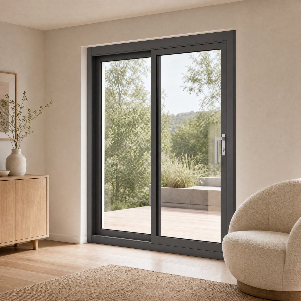
- The corner is three joints in one: a structural connection, the turn of the drainage path, and the junction of two gasket runs. A fabrication that satisfies one and not the others passes a factory check and fails on a wet elevation.
- A crimped corner is a mechanical interlock, not a weld. Its capacity comes from cleat geometry biting into the profile wall, so wall thickness, cleat design, press alignment and mitre accuracy are the variables, and none of them appear on a product datasheet.
- Screw-port cleating trades process robustness for inspectability: the fasteners can be seen, torqued and re-checked, but the joint is only as good as the operator discipline behind the ports.
- PVC-U and aluminium do not share a corner technology. uPVC corners are normally fusion welded and cleaned; aluminium corners are normally mechanical. A quotation that treats them as interchangeable is describing a different product.
- Sealant injected into a corner can seal the joint and block the drainage path at the same time; the corner is the one place where the water path has to turn and the seal has to stop.
- Sash weight runs into the hinge-side stile and then into two corners; on a heavy glazed leaf the corner joint, not the profile, is the weak link in the chain.
- Product standards such as EN 14351-1 and AAMA/WDMA/CSA 101/I.S.2/A440 assess the assembled product, and profile standards assess the profile. Neither certifies a corner joint in isolation, so the joint has to be verified by inspection and by the fabricator's own process control.
1. Why the Corner Is the Hardest Joint in a Window
A window frame looks like four straight profiles. It is in fact a closed loop that has to act as a single structural ring, keep a constant sight line, carry glazing and hardware, and route water out of the assembly - and every one of those duties passes through a mitre joint at each corner. Nothing else in the product has to do three jobs at once in a space of a few centimetres.
The mitre is also the joint nobody sees again. Once the frame is fixed into the opening and the architrave or plaster line closes over the reveal, the interior corner is concealed, and the exterior corner is only visible if the building is viewed from an angle that the client will never use. A corner that starts to open, or that lets water into the frame section, gives no early warning. The first evidence is usually a stain on the plaster return, a soft patch in the lining, or paint blistering on the exterior reveal in the season after installation, and by then the frame is fixed, glazed and decorated.
There is a second reason the corner deserves its own specification line. It is the only part of a window where the manufacturing process, rather than the profile catalogue, determines performance. Two fabricators can buy the same extrusion, the same gasket and the same hardware, and produce corners with materially different behaviour depending on how the mitre is cut, how the cleat is applied, whether the corner is sealed and where the drainage outlet sits. A datasheet describes the section. It never describes the joint.
2. Three Ways to Make an Aluminium Mitre, and One That Is Not Aluminium
Aluminium frames are joined mechanically, and there are three common methods in commercial window and door fabrication. Each leaves a different signature in the finished product and a different failure mode in service.
- Crimped corner. A knurled or serrated corner cleat is inserted into the hollow chambers of both mitred members, and the outside of the profile is pressed hydraulically so that the wall is forced into the cleat. The joint is an interference fit, and it is entirely dependent on the press, the tooling and the wall thickness it is working with.
- Screw-port cleat. A corner cleat - often aluminium or a reinforced polymer - is inserted and then locked by screws driven through pre-drilled ports in the profile, which are afterwards closed with colour-matched plugs. The connection is visible before the plugs go in, and it can be re-torqued or dismantled.
- Mechanical corner block or connector. A shaped block or a pin-and-sleeve connector bridges the two members and is fixed by screws or by expansion. This is common on larger sections, on doors with heavy leaves, and on systems where the profile geometry leaves no room for a conventional cleat.
uPVC frames sit outside this list, and buyers regularly conflate the two. A uPVC frame corner is normally fusion welded: the two mitred ends are melted and pressed together, the weld bead is cleaned off, and the joint becomes continuous material. A welded corner has no cleat and no screws, and it cannot be inspected by looking for press marks; its quality shows in bead removal, in whether the weld has been over-heated, and in the strength of the welded joint, which is tested by a method specific to PVC-U profiles. Systems described as mechanically jointed uPVC use corner blocks and screws instead, and those should be read as a different product line rather than as a variant of the welded one.
The practical consequence is that a specification has to name the joint method it expects. A clause that says only that frames shall be mitred and corner-jointed permits all four approaches, including the ones the buyer did not have in mind.
3. What a Crimped Corner Actually Depends On
Crimping is the most common aluminium corner in the market and the least documented. Its capacity does not come from the cleat being strong; it comes from the profile wall being locally forced into the cleat's serrations, so that the two members cannot separate or rotate. Four things decide whether that happens properly.
Wall thickness in the cleat zone. A crimp needs enough metal to deform into the serrations without buckling or tearing. Where the wall is thin, the cleat has little to bite, the press either tears the wall or produces a joint that looks closed and carries almost nothing. This is one of the reasons procurement specifications name a minimum profile wall thickness: the number is usually justified on wind load grounds, but it also governs whether the corner can be made at all.
Cleat design and fit. Cleats differ in serration pattern, length and the clearance they leave in the chamber. A cleat that is loose in the chamber rocks; a cleat that is too tight distorts the profile before the press closes. Both reduce the effective interference.
Press pressure and tooling alignment. The press has to indent at the correct points on both faces, at the correct depth, squarely to the profile. Tooling that is worn or out of alignment produces a corner that is visibly asymmetric, and asymmetry at the corner is where the frame will first go out of square under load.
Mitre accuracy and cut quality. A 45-degree cut that is half a degree out leaves a wedge-shaped gap that no amount of crimping closes. Burrs on the cut face hold the members apart, and swarf left inside the chamber prevents the cleat seating. The joint that results is tight at one face and open at the other, and the open face is usually the exterior.
None of this can be read from a product catalogue. It can be read from the frame in front of you: even press marks on both faces, a mitre line that is a consistent hairline rather than a gap tapering from one edge to the other, and a corner that has not been touched up with sealant to hide a joint.
4. Screw-Port Cleating: The Joint You Can Inspect
Screw-port cleating moves the uncertainty from the press to the operator, and that is not automatically an improvement. The advantage is inspectability: the cleat is a known component, the screws can be seen, the thread engagement can be checked, and a corner that has loosened in transit can be re-tightened rather than replaced. The disadvantage is that the joint's capacity is now a function of discipline - correct screw length, correct torque, thread engagement in the cleat rather than in the profile wall alone, and ports that are properly sealed afterwards.
Screw length is the detail that goes wrong most often. A screw that is too short engages only the first threads of the cleat and carries load on a few turns; a screw that is too long bottoms out in the chamber, leaves the joint loose and may penetrate into the glazing rebate or the drainage channel. Neither condition is visible once the port plug is fitted. Torque matters for the same reason: under-torqued screws allow the joint to work and fret, over-torqued screws strip the cleat and the joint relies on friction alone.
The port plugs are part of the weathering system, not decoration. An open port is a direct path from the exterior surface into the frame chamber, and on the head or the windward jamb it admits water under exactly the pressure that the drainage design is trying to manage. Plugs that are loose, missing, or a different colour from the finish are a reliable indicator of how the rest of the joint was treated.
There is one more distinction worth writing into a specification. A screwed corner joint and a screwed repair are not the same thing. A frame that has been drilled and screwed on site after a corner opened has had its coating broken at the most exposed point, has had an unsealed hole put into a drainage chamber, and has usually been pulled back into square without addressing why it moved. Site repair of a corner is an admission that the factory joint was inadequate; it should not be presented as a maintenance item.
5. Gaskets, Sealant and the Turn of the Drainage Path
In a drained window the gasket is the primary barrier and the frame section is the secondary one. Water that passes the outer gasket lands in a chamber, drains through slots in the bottom rail, and leaves through weepholes on the exterior face. That entire route changes direction at every corner, and the corner is where the two systems can interfere with each other.
Take the gasket first. A gasket run that is cut and butt-jointed at the corner leaves a compression gap that opens under thermal cycling, and the gap is at the one point where two directions of movement meet. Corners that are moulded, vulcanised or formed as a continuous loop eliminate that gap, and they are the only gasket detail that stays closed when the frame moves. A butt joint that has been sealed with a mastic bead instead is a service-life decision, not an equivalent: the bead adheres to a compressible surface, ages under UV on the exterior, and is the first thing to fail at a corner.
Then the sealant. Injecting sealant into the corner cavity is a necessary step on most aluminium systems, and it is also the step that most easily closes the drainage path. The corner seal must stop water travelling inside the section from the exterior into the interior, and it must not block the bottom-rail drainage channel or sit upstream of a weephole. The correct order is to seal the joint, then confirm by inspection that the drainage route past the corner is still open; the incorrect version, which is common, is to fill the corner until it is watertight in every direction, including the one that was supposed to let water out.
Weephole position is the third part of the same problem. The outlet has to sit on the exterior face, downstream of the inner gasket line and downstream of the corner seal, and it has to be large enough to pass the water the cavity can collect without the water level rising to the inner gasket. Outlets covered by a sill upstand, blocked by a render bead, or drilled only on one side of a wide bottom rail are all the same failure, and the symptom appears as a damp patch at the bottom corner of the frame on the windward elevation.
6. The Load Path Through a Corner
Corner joints are usually discussed as a water problem, and their structural role gets less attention than it deserves. On an opening sash or a door leaf, the dead load of glass and hardware enters the profile at the hinge side, travels down the stile, and is transferred into the frame at two corners. On a fixed light, wind pressure and suction arrive at the glazing, pass through the beads and the gasket line into the profile, and leave through the perimeter fixing; the corners of that perimeter carry the change of direction.
The relevant numbers are small but they are not trivial. A large triple-glazed leaf can weigh enough that the bottom hinge-side corner is carrying a significant share of that load permanently, in one direction, for the life of the building - a loading case quite different from wind, which reverses. A corner joint that was checked only against wind pressure has not been checked against the dead load case at all, and the symptom of an under-designed corner in that position is a leaf that drops out of square over a few seasons, with the lock side dragging and the diagonal measurement opening up.
The same logic explains why corner joint design and hardware layout have to be considered together. Where the hinges are fixed into the reinforcement of one stile, the corner joint is what keeps that stile aligned with the head and sill; where the section has no continuous reinforcement across the corner, the joint alone has to hold the geometry. That is a perfectly normal arrangement in light residential work and a poor one in a tall or heavily glazed door, and the difference is visible in the specification as much as in the frame: a reinforced corner block or a corner gusset is not an upgrade anyone notices on site, but it is the component that keeps a heavy leaf square.
7. Failure Modes That Surface After Handover
Corner problems rarely appear during installation, because the frame is still square, the sealant is still new and the weather has not yet cycled. They appear in the first two or three seasons, and they present in a small number of recognisable ways.
- A hairline gap that opens and closes. The mitre line becomes visible on the exterior face in hot weather and closes in cold. This is a joint that was never fully locked - a light crimp or an under-torqued screw-port cleat - working against the thermal movement of the members. It is the earliest and cheapest-to-miss warning.
- Water at the bottom corner, not the middle of the sill. Drainage that works in the centre of the bottom rail but fails at the corner points to a blocked or misplaced weephole, a corner seal poured across the channel, or a corner that is not closed at all and admits water behind the gasket line.
- Corrosion at the cut end. Coated aluminium is protected on its faces and bare at the mitre. A corner that has never been sealed exposes that cut edge to the weather, and the first sign is a line of white corrosion product along the joint, followed by coating detachment around it. The corrosion is cosmetic for a long time and structurally relevant eventually, because the material it is consuming is the material the cleat is biting.
- A cracked or opened corner after transport. Frames travel stacked, and the corner is the point that takes the impact. Corner protectors and a loading plan that keeps frames off their edges are specification items; without them the corner arrives damaged and the repair is a site job.
- Powder coat cracking at the crimp. A crimp that was pressed too hard, or pressed on a coated face with the wrong tooling, leaves the film cracked or crazed exactly at the deformation. That is a coating failure waiting for a coastal or polluted environment, and it is only visible at close range in raking light.
8. What a Buyer Can Verify Before the Container Is Loaded
Because the corner is a process, not a product, verifying it means looking at process evidence rather than certificates. Everything below can be done in a factory visit of two hours, and it addresses the failure modes in the previous section directly.
Cut a corner open. Ask for a scrap frame and section it through a corner in both directions. What matters is whether the cleat has been deformed into the wall along its full length, whether the wall has torn, and whether the sealant has reached the joint rather than sitting on top of it. A fabricator who will not cut a sample is telling you something.
Measure the closed loop. Take the two diagonals of a finished frame and of one sash. Equal diagonals within the fabricator's own tolerance, checked on the flat, are the fastest available check that the corners were pressed squarely. Do the same check on frames after transport on a repeat order; it is the cheapest way to find a packing problem before installation.
Look at the evidence left on the surface. Even press marks on both faces, mitre lines of consistent width, plugs seated flush, no sealant smeared over a joint to disguise a gap, and no drilling on a corner. Each of those is a visible proxy for a process.
Confirm the drainage path. On a sample, pour water into the bottom-rail cavity and watch where it exits. It should leave through the exterior weepholes within seconds and it should not appear at the inner gasket line. This is a workshop check, not a substitute for a laboratory water test, but it finds the corner-seal error that laboratory testing on a hand-built specimen will never show.
State the standard's actual scope. Product standards - EN 14351-1 in Europe, AAMA/WDMA/CSA 101/I.S.2/A440 in North America, AS 2047 in Australia - assess the performance of an assembled, specified product, and the classification applies to the configuration tested. Profile standards describe the profile, and the PVC-U welded corner test method addresses welded joints in PVC-U rather than aluminium. None of them certifies that a given factory's crimp is sound on a given day, which is why the specification should carry the joint method, the cleat type, the corner seal requirement and the drainage check as explicit clauses, and why the inspection should be a witness point rather than a document review.
Explore OPPGATE Aluminum Windows
Thermal break aluminum sliding, casement, tilt-and-turn and panoramic window systems for global residential and commercial projects.
View All Aluminum Windows Models
Planning a Commercial or Villa Project?
Send your window schedules or architectural CAD drawings to the OPPGATE engineering team for a prompt, certified quotation and structural review.
Request an Engineered Quotation